1 Introduction
The SAFR SCAN integration with RIO allows for real-time, high-accuracy biometric authentication, ensuring that only authorized individuals gain access to restricted areas. SAFR SCAN uses the imported Cardholder picture, converted into a biometric signature, to verify a person identity when presented at a SAFR SCAN reader. SAFR SCAN supports the RIO protocol. SAFR SCAN is able to connect to Genetec Cloud Link and control a door by performing physical access control panel functions (Door lock, REX and Door Contact). In this way, SAFR SCAN is able to act as a door controller without the need for a separate panel.
This guide does not describe how to configure SAFR to import cardholder and credential data from Genetec Security Center. To know about Attribute mapping, person and credentials sync and API access, refer to the Genetec - SAFR Cardholder Integration Guide available at http://docs.real.com.
To integrate and use the SAFR SCAN RTSP video feed in Genetec Security Center for surveillance please see the SAFR Genetec VMS Integration Guide.
For complete SAFR and SAFR SCAN documentation please visit http://docs.real.com.
1.1 System Requirements
Genetec has the following system requirements:
-
Genetec Security Center Version 5.7 to 5.13
⚠️ Consult SAFR support before upgrading Genetec beyond supported versions. - One or more Genetec Cloud Link devices.
- SAFR SCAN supports all models of Cloud Link.
- Genetec CloudLink 3.0.0 through 3.2.506.0
SAFR has the following system requirements:
-
SAFR Platform Version 3.28 or later
- Each machine running the SAFR Server must meet the following requirements:
- Windows 10, Windows Server 2016 or later
- i5 or Xeon Silver 4216 or faster with at least 4 cores allocated to SAFR Computer
- 16 GB System RAM
- 1 TB Storage
- SAFR SCAN Firmware version 2.2 or later
- For systems running more than 50 SAFR SCAN, please consult SAFR Technical Support at support@safr.com or http://support.safr.com
1.2 Integration overview and System requirements
1.2.1 Video Tutorial
Following is a 10 minute overview of the SAFR RIO integration to Genetec.
1.2.2 Integration overview
This guide describes:
- Detailed instructions for integrating SAFR SCAN with Genetec Security Center to enable biometric authentication.
- Step-by-step guidance on configuring SAFR SCAN as a RIO device.
This guide does not cover cardholder and credential synchronization. See Genetec - SAFR Cardholder Integration Guide available at http://docs.real.com. This document assumes that cardholder integration is already configured.
1.3 Integration Architecture
A typical integration architecture:
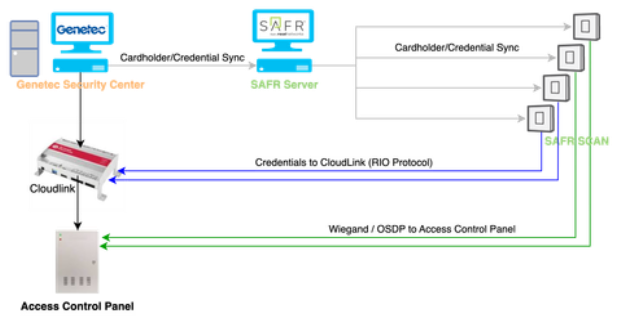
This diagram represents an integrated access control system that leverages Genetec Security Center, SAFR Server, and Cloud Link to facilitate seamless and secure authentication through a combination of facial recognition and credential-based access.
The diagram demonstrates two types of ways in which SAFR SCAN integrates to Genetec for opening doors.
- Low voltage Wiegand or OSDP Wiring - SAFR SCAN authenticates a face and send credentials over Wiegand or OSDP to the physical access control panel (this is not the subject of this document)
- Cloud Link via IP Networking - SAFR SCAN authenticate the face and either unlocks door directly (empowered mode) or sends credentials to Cloud Link via IP networking (this is the subject of this document).
In both cases, the process begins with Genetec Security Center, which serves as the primary system for managing cardholder information and access credentials. These cardholders and credentials are synchronized to the SAFR Server and pushed out to the SAFR SCAN devices. SAFR SCAN is then is responsible for handling facial recognition authentication.
1.3.1 Operation Modes
SAFR RIO integration operates in two modes; empowered and cooperative mode. These are described below.
1.3.1.1 Empowered mode
When operating in empowered mode, the SAFR SCAN device can make independent access control decisions without relying on an active network connection.
The device operates independent of connection to Cloud Link. All cardholders and credentials are loaded on the device and decisions for unlocking door are made locally. This method does not allow for some advanced schedules or panel rules such as two-man-rule. This option requires additional space on the device to store access levels which will reduce its overall capacity depending on the number of access levels. Space required for access levels will reduce the total cardholder limit from the normal 50,000 (mask or no mask) or 100,000 (no masks) models.
In this mode, SAFR SCAN acts as a panel. Only in this mode will SAFR SCAN perform actions on the door such as activating the door strike or accepting input signal from a REX (Request to Exit button).
In empowered mode, data flows from Genetec Security Center to SAFR SCAN and SAFR SCAN controls doors directly through its Door State and REX inputs and Door Relays.
1.3.1.2 Cooperative mode
In contrast with empowered mode, when operating in cooperative mode, SAFR SCAN devices defer access decisions to the connected access control panel via Cloud Link.
The device defers access control decisions to connected Cloud Link device. Due to the dependence on the Cloud Link device, if connection to Cloud Link is lose, then the function of the device is lost as well. Because access levels do not need to be stored, the device can reach the stated capacity of 50,000/100,000 cardholders.
In this mode, SAFR SCAN depends upon the physical access control panel to unlock doors and receive inputs such as REX. This is accomplished by sending person credentials to the Cloud Link device.
In cooperative mode, data still flows from Genetec Security Center to SAFR SCAN. Once authenticated, data then flows to Cloud Link via IP networking as shown by the blue lines in the diagram above.
1.3.2 How it works
When a user attempts to access a secure area, they interact with a SAFR SCAN device, which captures their facial data and compares it against the face. The face and the credentials stored locally on the SCAN device. The access mode of the SAFR SCAN can be either "empowered" or "cooperative", defining how access decisions are made. In empowered mode, the SAFR SCAN itself is authorized to make access control decisions independently. In contrast, in cooperative mode, the SAFR SCAN defers access control decisions to the connected access control panel or host controller by sending credentials to Cloud Link and allowing it to evaluate access rules and perform necessary actions. This flexibility allows the system to be adapted to different security requirements, where some environments may benefit from independent decision-making at the device level, while others require centralized authorization.
2 Genetec Configuration
This section assumes you have a Cloud Link device provisioned and available. You will need the IP Address and Credentials of this Cloud Link device.
2.1 Enable RIO Configuration Tab
- Enable the RIO configuration tab in Config Tool for your Cloud Link unit using the following URL command: https://[Unit IP]/Features/DuiRIO/Enabled/Set?value=true, where [Unit IP] is the IP address of your Cloud Link unit.
2.2 Create RIO API User
To ensure the Genetec Synergis Cloud Link is secure, create a specific user account for the RIO API. This user account can limit the access rights of the RIO API calls to the channel.
To create a specific RIO API user:
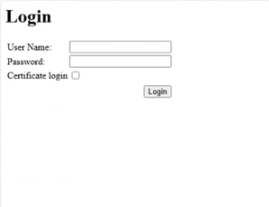
- In your web browser, go to https://[Cloud link IP]/smc/accountmanagement.html , where [Cloud Link IP] is the IP address of your Cloud Link unit.
- Log in using the admin credentials for your Cloud Link Device.
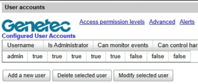
- Click Add a new user.
-
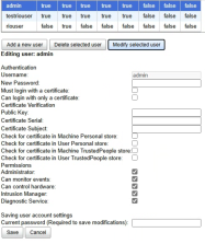
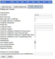
In the Authentication section, enter a username and password for the new user. There are two choices for what permissions this user is granted.
- Grant user only monitor permission and include an Admin user with "Administrator" and "Can control hardware" permission
-
Grant user all three permissions:
- Administrator
- Can monitor events
- Can control hardware
|
Admin User |
Monitor only user |
|
|
|
![]()
2.3 Connect SAFR SCAN To Cloud Link
After you create a RIO API user, you need to set up RIO connection. You do so by connecting SAFR SCAN to the Cloud Link device. SAFR SCAN takes care of configuring a necessary hardware in Genetec. The configuration of that hardware is dependent upon the selections made when connecting SAFR SCAN to your Cloud Link device:
- Open SAFR Desktop
- Go to Tools menu > Video Feeds
- Select Edit Operation Settings from the "…" menu for the SAFR SCAN you wish to connect
-
Click on RIO page
The RIO is disabled by default.

-
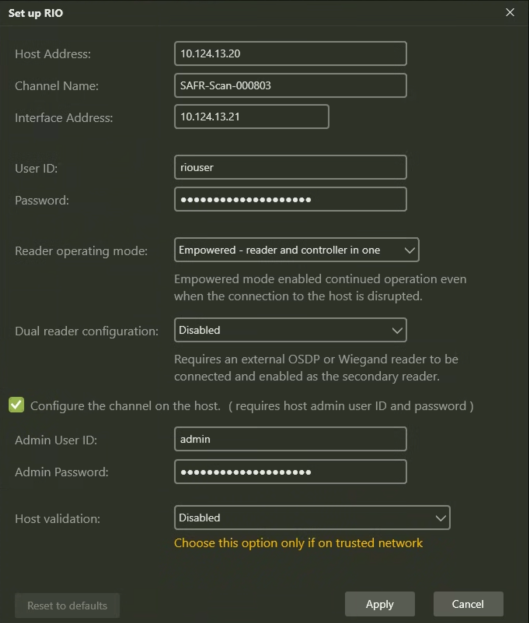
Enable the RIO connection and configure as follows (settings are explained below):
-
Once you enable RIO, you need to set up RIO for the first time. All properties will be preserved for each device and loaded into the dialog upon enabling.
The parameters in the config box are as follows:
|
Host Address |
Cloud Link device address |
|
Channel name |
RIO channel name. This is the name of the SAFR SCAN device that appears on the Genetec config tool. Example above uses the default name of SAFR SCAN but in practice you would want to use a logical name that indicates what door the SAFR SCAN is mounted at. |
|
Interface Address |
RIO interface address. This is the address of SAFR SCAN. If left empty, SAFR SCAN's IP Address is used. |
|
User ID |
The user ID on the Cloud Link device that was created above. This is used to communicatewith the Cloud Link. See Create RIO API User above for more information. |
|
Password |
The password corresponding to the Cloud Link user id above. |
|
Reader Operating Mode |
Possible values: "empowered" and "cooperative". Empowered mode The device operates independent of connection to Cloud Link. All cardholders and credentials are loaded on the device and decisions for unlocking door are made locally. This method does not allow for some advanced schedules or panel rules such as two-man-rule. This option requires additional space on the device to store access levels which will reduce its overall capacity depending on the number of access levels. Space required for access levels will reduce the total cardholder limit from the normal 50,000 (mask or no mask) or 100,000 (no masks) models. In this mode, SAFR SCAN acts as a panel. Only in this mode will SAFR SCAN perform actions on the door such as activating the door strike or accepting input signal from a REX (Request to Exit button). Cooperative mode The device defers access control decisions to connected Cloud Link device. Due to the dependence on the Cloud Link device, if connection to Cloud Link is lose, then the function of the device is lost as well. Because access levels do not need to be stored, the device can reach the stated capacity of 50,000/100,000 cardholders. In this mode, SAFR SCAN depends upon the physical access control panel to unlock doors and receive inputs such as REX. This is accomplished by sending person credentials to the Cloud Link device. |
|
Dual Reader configuration |
This setting allows a 2nd reader to be configured on the door. Most often this is used to connect an outbound badge reader to the inside of the door. This reader is connected via OSDP. Credentials are validated and door action triggered accordingly. Possible values: "disabled", "primary-in-secondary-out", "primary-out-secondary-in".
|
|
Configure the channel on the host |
Check this to create and configure the channel on the Cloud Link device. This should always be set. |
|
Channel admin User ID and Channel admin Password |
Optional user id and password for device configuration. This is only needed if the User Cloud Link id and password is only set for monitor permission. |
|
Host validation |
Used to set the type of SSL certificate on the Cloud Link device. Setting this to Disabled will disable validation of the SSL certificate. |
-
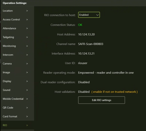
You will see the connection status as OK. This confirms the RIO connection setup.
- If RIO status will be reported as “Initializing”, as the connection is established
- If RIO status is changed to “OK” once the connection is successfully established and the hardware is fully configured on the Cloud Link device.
- If RIO status is set to “Error” with a short error message if there are connections, authorization or other errors creating the hardware.
Following shows SAFR SCAN successfully connected with "OK" status.
As mentioned, once connected, the nec![]() essary hardware is created in Genetec. You can view this under Hardware in the RIO tab for the Cloud Link Device as shown below:
essary hardware is created in Genetec. You can view this under Hardware in the RIO tab for the Cloud Link Device as shown below:
Go to Access Control. Select the Cloud Link device on the left. Go to the Hardware Tab and click RIO page.
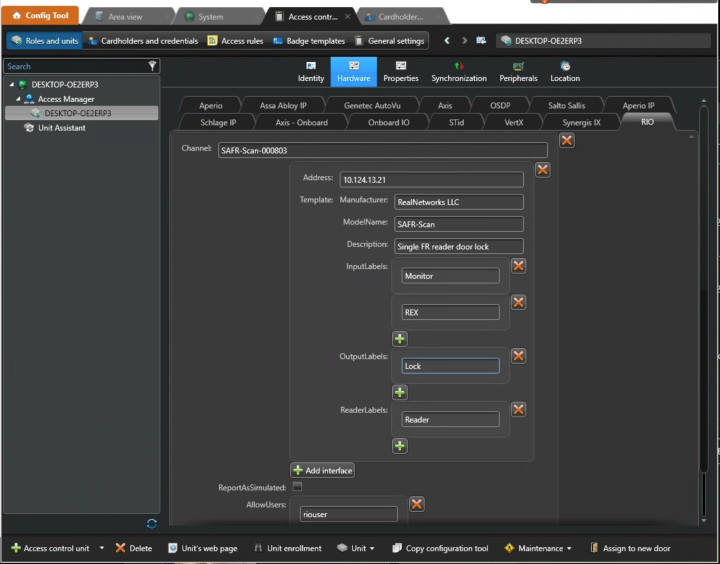
Observe that the Channel name is the name provided in SAFR SCAN RIO configuration dialog. The Address is the IP Address of SAFR SCAN. Multiple inputs/outputs are created to accommodate SAFR SCAN device configuration options as explained below. These are:
- Monitor - Door status (open / closed)
- REX - Request to Exit which is controlled by connecting to the appropriate PINS on SAFR SCAN wiring connector.
- Lock - Door strike or maglock controlled by SAFR SCAN's Normally Open or Normally Closed dry contact relays
- Reader - The secondary reader connected to SAFR SCAN via OSDP in wiring.
2.3.1 Configure SCAN Door I/O
By default, SAFR SCAN has all settings that may expose security vulnerabilities disabled. To enable SAFR SCAN to control doors as described in previous section (Lock, Door Status, and REX). To enable these options, go to Operation Settings for the SAFR SCAN Device ("…" menu > Edit Operation Settings) and click on "Door I/O" on the left.
2.4 Configure Door with SAFR SCAN Door I/O in Genetec
Once SAFR SCAN has connected, necessary hardware is created. This hardware can then be attached to a door in Genetec Config Tool. This section outlines briefly the hardware made available by SAFR SCAN.
2.4.1 Set Door I/O
- In your SAFR console, go to Operation Settings in Video Feeds
- Click on Door I/O on left hand side
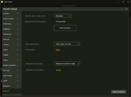
2.4.1.1 Electric door strike relay
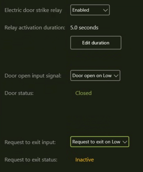
It Indicates if door relay activation is enabled. 
When selected, option to set suitable duration for relay activation is provided. The door relay duration is the duration in seconds the relay remains open once activated. 
2.4.1.2 Door open input
Configures the door open input signal. See wiring diagram below for information on how to connect the door state sensor to SAFR SCAN. Options are:
- Disabled - Door input signal is not active.
- Door open on Low - SAFR SCAN reports the door as open if zero voltage is applied to the connection.
- Door open on High - SAFR SCAN reports the door as open if voltage is applied to the connection.
2.4.1.3 Request to Exit input
Configures the REX input signal. See wiring diagram below for information on how to connect the door state sensor to SAFR SCAN. Options are:
- Disabled - REX input signal is not active.
- Request to exist on Low - SAFR SCAN will unlock door if zero voltage is applied to the connection.
- Request to exist on High - SAFR SCAN reports the door as open if voltage is applied to the connection.
Following shows all three controls in enabled state:
2.5 SAFR SCAN Door I/O Wiring
2.5.1 SC100 / SC200 Models
Following diagram demonstrates wiring for Door I/O on SC100 and SC200 models.
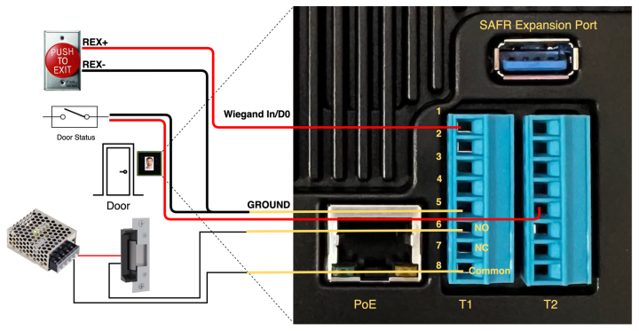
2.5.1.1 REX Input
- Positive input goes to PIN1 on Terminal Block 1 (Wiegand D0 Input)
- Ground input goes to PIN5 on Terminal Block 1
2.5.1.2 Door Status
- Positive input goes to PIN5 on Terminal Block 2 (TTL input)
- Ground input goes to PIN5 on Terminal Block 1
2.5.1.3 Door Relay - Normally Open Circuit
SAFR SCAN provides a dry contact relay (power must be supplied externally) to control the door lock. Following connections are required for the Normally Open Circuit.
- Positive input goes to PIN6 on Terminal Block 1
- Ground input goes to PIN8 on Terminal Block 1 (common)
2.5.1.4 Door Relay - Normally Closed Circuit
SAFR SCAN provides a dry contact relay (power must be supplied externally) to control the door lock. Following connections are required for the Normally Closed Circuit.
- Positive input goes to PIN7 on Terminal Block 1
- Ground input goes to PIN8 on Terminal Block 1 (common)
2.5.2 SC50 Models
Following diagram demonstrates wiring for Door I/O on SC50 model.

2.5.2.1 REX Input
- Positive input goes to Green with black segment wire (Wiegand D0 Input)
- Ground input goes to Solid Black wire (Ground)
2.5.2.2 Door Status
- Positive input goes to Solid White with black segment wire (Wiegand D1 Input)
- Ground input goes to Solid Black wire (Ground)
2.5.2.3 Door Relay - Normally Open Circuit
SAFR SCAN provides a dry contact relay (power must be supplied externally) to control the door lock. Following connections are required for the Normally Open Circuit.
- Positive input goes to Violet wire (Normally Open)
- Ground input goes to Brown wire (common)
2.5.2.4 Door Relay - Normally Closed Circuit
SAFR SCAN provides a dry contact relay (power must be supplied externally) to control the door lock. Following connections are required for the Normally Closed Circuit.
- Positive input goes to Blue wire (Normally Closed)
- Ground input goes to Brown wire (common)
2.6 Configuring a Door in Genetec
As described above, once connected, SAFR SCAN creates all the necessary Door I/O hardware for door configuration in Genetec Config Tool. This section briefly outlines how the Door I/O is leveraged in Genetec.
Creating a Door
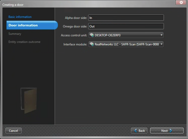
A new door is created in Area View > Add entity > Door. When creating a door in Genetec, the SAFR SCAN device will be listed as an Interface Module (prefixed with RealNetworks) within the Cloud Link device as shown below in the create door wizard
In the Hardware tab, the Door I/O components created by SAFR SCAN can be selected:
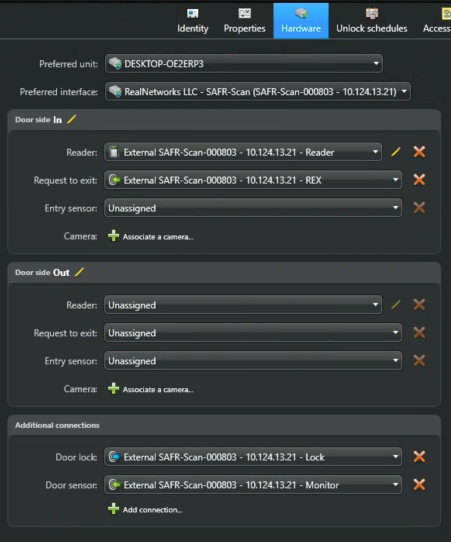
Above shows the SAFR primary reader, Door Lock, REX and Door I/O created above are selected.
In above case, had SAFR been configured for a secondary reader, it would appear in the Out Reader option.
2.7 Access Roles
Access Roles play a key role in which cardholders are synchronized to the readers in both empowered and cooperative modes and allows SAFR to make independent decisions in empowered mode.
This section outlines the steps to configure access roles within Genetec Synergis for SAFR RIO integration.
2.7.15.1. Access the Role Configuration Panel
- Open Genetec Security Center Config Tool.
- Navigate to Access Rules in th,ke left-side panel.

- Select Access Control > Access Rules.
2.7.25.2. Create a New Access Role
- Click Add an Access Rule.

- Enter a descriptive name for the access role (e.g., "SAFR Facial Recognition Access").
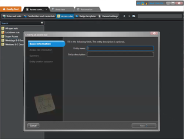
- (Optional) Provide a description for the role.
2.7.35.3. Define Access Conditions
- Under the Access Permissions section, click Add Entities.
- Select the doors or areas controlled by Synergis where the SAFR integration will be applied.
- Set the schedule for access (e.g., 24/7, business hours).
- Under Authentication Mode, choose Facial Recognition to ensure access is granted based on SAFR validation.
2.7.45.4. Assign Users or Cardholders
- Navigate to the Cardholders or User Groups section.
- Click Add Cardholders and select the users who should have access via SAFR.
- If needed, assign the role to an existing user group for easier management.
3 Troubleshooting
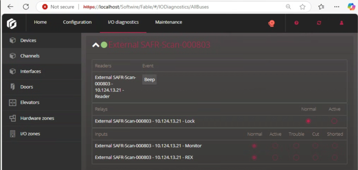
Status of the hardware setup in Genetec can be checked via the I/O Diagnostics > Channels screen as shown below.
