1 How it works
SAFR SCAN integrates into your existing Physical Access Control System (PAC). SAFR SCAN is mounted next to the door and connected to the PAC Panel via Wiegand or OSDP as shown in the graphic below.

SAFR SCAN sends the user credentials to the PACS Panel when a valid user appears at the door. The PACS Panel then evaluates if the user should be granted access based on their access clearances and if so, unlocks the door. For situations where a PACS Panel is not practical, SAFR SCAN can also unlock a door directly via the door latch Relay.
Users and their credentials are added to SAFR SCAN via the PACS software. As users and credentials are added or updated in the PACS software, SAFR automatically updates the local database on each SAFR SCAN reader with the latest user records to maintain synchronization with the PACS software.
In addition to the basic PACS integration, SAFR SCAN also supports the following:
- Enrollment from device, from an image file or webcam
- BLE reader to support Mobile Credentials and Universal RF Card Reader
- IR and white light projectors for low light environments
- Direct camera control for extreme back light environments
- RTSP Output for integration to VMS
- Tailgating detection, person counting and more
2 SAFR SCAN First Run
This section describes powering up and testing your SAFR SCAN reader.
2.1 Prerequisites
SAFR SCAN requires the following:
- A SAFR SCAN device
-
A door connected to one of the following:
- A Wiegand physical access control (PAC) panel
- An OSDP PAC panel
- A relay
- A PC or Mac with a web browser (for configuration)
2.2 Unbox SAFR SCAN
Unbox the SAFR SCAN device (the “reader”). Take note of the MAC Address (you will need this to create our Software Download account.
![]()

MAC Address
2.3 Power up SAFR SCAN
-
Plug a PoE cable into your SAFR SCAN device.
-
The SAFR SCAN device relies on PoE for its power.
- Alternatively, SAFR SCAN can be powered via the 12V Auxiliary power terminals.
- Ensure that your SAFR SCAN device is connected to the same network as your PC or Mac machine.
-
The SAFR SCAN device relies on PoE for its power.
-
When your SAFR SCAN device turns on, its IP address appears on its screen momentarily.

- Take note of the IP address; you’ll need it in the next step.
- The SAFR SCAN device defaults to DHCP, but if the device is unable to obtain a dynamically allocated address, then it defaults to 10.10.10.10 or an IP in the 169.254.x.x range.
-
Open a web browser on your PC or Mac and go to http://IP_ADDRESS (where IP_ADDRESS is obtained from the previous step). This will take you to the SAFR SCAN Console.
- You may be presented with a browser security warning about the default SAFR SCAN self-signed CERT. This is normal. See SAFR SCAN SSL CERT Security Warning in the SAFR SCAN Administration Guide for more details.
- If needed, see SAFR SCAN Networking in SAFR SCAN Administration Guide for information on connecting to SAFR SCAN without DHCP and setting SAFR SCAN to a fixed IP Address.
-
Click “Set Up System Login” when prompted and complete form.

- The username is always 'admin'
- The email address can be used to reset the device password. See Administrator Guide for details.
- When complete, login with the username 'admin' and the password set in previous step.
![]()
-
Update Firmware to latest (System > Update).
- If online, click “Check for updates” and select latest firmware version
-
 Else, download firmware from http://safr.com/portal > Downloads
-
Confirm Structured Light Calibration
- Open Live tab. Change video preview dropdown to ‘Face 3D”
-
Stand between 1 to 3 feet from the device and verify contour map of face looks valid. See https://docs.real.com/access/guides/articles/checking_calibration for details.
- If the date and time is off by more than a few minutes events may not appear on the timeline making it appear as the reader is not functioning. Check Date and Time on the System tab. An NTP server is strongly recommended to ensure device clock is accurate. SAFR Server version 3.28 or later will correct device time if off by more than 30 seconds.
3 SAFR SCAN Web Console Quick Tour
3.1 Live View
The Live View provides a real time view of activity on the reader as shown below.

Live video from the reader's camera appears on the left and events appear on the right. Initially you will only see “Stranger” events until faces are enrolled which is covered in the next section.
3.2 Enroll a person into SAFR SCAN
You can either enroll people by using an uploaded image of their faces or by using the camera on the SAFR SCAN device. See the SAFR SCAN Console’s People tab documentation for details on how to use an uploaded facial image to enroll a person.
3.2.1 Upload Face Image
- Open SAFR SCAN Web Console as described above.
- Navigate to the People screen
- Click “Add” button in upper right
-
In the dialog provided, chose image file and enter user information as shown below.

At a minimum, set first or last name and Access Clearance. Optionally provide Facility ID and Card ID. - Click Save Changes and the new person record will be added.
3.2.2 Enroll at the Reader
- Open SAFR SCAN Web Console as described above.
- Navigate to the Live tab
- Have a person stand 1 to 3 feet in front of the SAFR SCAN device, and have them look directly at the reader’s camera.
-
In the live tab, click “Enroll” and enter the user information in the dialog shown.

Access Clearance must be set or SAFR SCAN will not grant access. - Click OK to add the new person record.
3.2.3 Test Face Matching
- Have the enrolled person stand 1 to 3 feet in front of the SAFR SCAN device and have them look directly at the device’s camera.
- The LED ring should light up green indicating that SAFR SCAN has seen an authorized person.
- The Live tab of the SAFR SCAN’s Console should show that the enrolled person has been granted access.
3.2.4 Did it work?
Check troubleshooting section below if not.
At this point your SAFR SCAN device is functioning and ready to be installed.
3.3 Test Calibration
For optimal performance, the structured light projector must be well calibrated. In rare cases, devices may get out of calibration due to a shock. To ensure best performance, test structured light calibration as follows:
- Open Live tab.
- Change the dropdown below the video preview region to ‘Face 3D”
- Stand between 1 to 3 feet from the device
- Verify contour map of face looks valid as follows:

If device appears out of calibration, see https://docs.real.com/access/guides/articles/calibrating_structured_light_sensor.
3.4 People Tab
People Tab displays any person records that have been enrolled on the reader.

You can use this tab to filter, view or edit person records. Once connected to SAFR Server, any person records on SAFR Server are downloaded to the reader depending on your filter settings. By default, for privacy reasons, face images are not downloaded to the reader but face matching will function as normal.
For security purposes, faces images are not stored on the device. Face images are maintained in SAFR Cloud. They person record will appear as a face silhouette with a square box around the face as shown below indicating that a signature exists but face image is not present. This can be changed in the device configuration.

3.5 Operation Tab
In this tab you will find settings to configure reader behavior. These settings are covered in SAFR SCAN Administration Guide. Below is a description of the most important options.
3.5.1 Access Control
-
Access Mode controls which authentication factors the reader will check. Available factors include Face, Access Card, Keypad and Mobile Credentials with combinations of above to support multi-factor authentication.
- Multi-factor authentication is performed on the reader. No need to configure the panel to coordinate different factors from different sources. For example, you can use this option to turn on Card AND Face authentication for IT rooms to improve security. Or you can change to options such as keypad for low security general use rooms such as staff only break room.
-
Spoofing protection level controls the degree of protection against impersonations using printed photos or masks.
- Standard works for most, even those with minor occlusions such as glasses or covid masks. Use this setting if you wish to strengthen your security (go to a higher mode) or improve ease of use and speed (go to a lower mode). You may want to consider disabling this feature on monitored doors (i.e. monitored turnstiles, doors with operators nearby) or internal doors for greatest convenience for your credential holders. The “Light (mask allowed)” mode is specifically designed for outdoor use cases with strong backlight.
- Access Denied Signal to Control Panel allows the administrator to configure a fixed credential to send to the panel if someone attempts an unauthorized access. SAFR also reports these events in its event history with face image of the person attempting access as well as the full scene image.
- Pass through Access Card to Control Panel when in single factor mode allows cardholders who are not added to the SAFR SCAN database to gain access by using the control panel to authorize access. When checked, faces and cards that are stored in SAFR SCAN will be authenticated locally, but any cardholder not present in SAFR SCAN will be authenticated by sending credentials from the presented access card to the panel and using the panel response (granted or denied) to grant access.
- Auto-enroll Access Card when used with Face Recognition as a single factor allows cardholders to enroll their face in SAFR SCAN by presenting a card. SAFR SCAN sends the card credentials to the control panel and augments the person record stored locally with a face image if access is granted by the panel.
- Unlock temporarily can be used to unlock the door remotely from SAFR Software. This feature uses a fixed credential to transmit to the panel as configured in Temporary Unlock Signal to Control Panel setting above.
- There are many other settings in this page such as control over how far away a face must be for face matching to occur, a method to activate the face matching process (for privacy reasons) by physically interacting with the device, and ability to prevent access if unauthorized persons exist in the background. See SAFR SCAN Administration Guide for more details.
3.5.2 Intercom
- Backlight compensation is SAFR SCAN's intercom feature turns SAFR SCAN into a SIP or WebRTC Intercom client. A Corresponding SIP or WebRTC Server is required. For SIP, a SIP account (extension and password) is required for inbound calls and a SIP extension may be used to allow SAFR SCAN to make outbound calls.
3.5.3 Camera
- Backlight compensation is SAFR SCAN's unique capability to directly control the camera's exposure (shutter speed and aperture) to ensure best lighting on the face. In most lighting conditions, Auto performs well. This setting allows you to give a hint to SAFR SCAN in conditions where there are extreme lighting conditions. Use this if SAFR SCAN recognizes the face but takes a while to show the green heart (anti-spoofing test) and present access granted message.
- Scene exposure region allows you to enhance the camera's ability to detect faces in cases where there is very strong backlight. This is a region on which SAFR sets the initial camera exposure when no faces exist in the view. This should be set to a region that has similar lighting conditions as the face. For example, if there is bright sky or light-colored concrete in a large portion of the view, select Custom and chose a region (even if very small) that is darker such as bushes or trees or an wall/overhang that is not exposed to direct sunlight. When set properly, the lighter colored background such as sky or concrete should appear washed out but faces appear well lit without shadows.
3.5.4 Display
- Display Mode or Display background when active can be used to turn off the display from echoing back the video of the credential holder as this behavior (seeing themselves on the screen) is sometimes unwelcome by users.
-
Activation distance will prevent the screen from activating in locations where unrelated foot traffic may be passing within activation distance of the reader.
?This setting does not prevent face matching. To control that, see SAFR SCAN Administration Guide. - Display image when inactive allows you to add your company logo on the screen.
- Keypad Layout and Keypad Code Size (number of digits for a PIN code) are cleverly tucked away at the bottom of the Display. These allow you to control the onscreen keypad.
There is a host of other very cool controls in the Display Tab. You are encouraged to explore on your own.
3.5.5 Sound
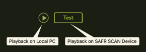
Sound tab has controls to customize the audio prompts on SAFR SCAN and the audio volume.
For each sound prompt, you can test the audio on local PC and on SCAN using the respective buttons:
3.6 System Tab
System Tab provides settings related to device. These settings are covered in SAFR SCAN Administration Guide. Below is a description of the most important options.
3.6.1 SAFR Server
This setting allows connection to SAFR Server for remote management, credential holder synchronization and event aggregation.
3.6.2 Video Streams
SAFR Camera provides RTSP video feeds that can be provided to 3rd party software such as a VMS. These are not required for the SCAN access functions.
Settings in the Video streams tab allow adjustment of the RTSP stream settings. To enable RTSP streaming, a password must first be set on the Security Tab. Until a password is set, the camera will not allow RTSP connections.
3.6.3 Network
This tab allows the network configuration to be modified. The camera default is DHCP. Network can be changed to static IP Address in this page.
3.6.4 Date and Time
By default, SAFR SCAN will use NTP to get its date and time. It default to pool.ntp.org. If not available, you may need to specify an internal time server (preferred) or set time manually. Click “Sync to Computer Time” to set time manually.
⚠️ If the date and time is off by more than a few minutes events may not appear on the timeline making it appear as the camera is not functioning.
3.6.5 Update
Use this tab to update the camera firmware. If the camera is connected to a public network, it will present a list of firmware versions to upgrade if available. Else, download firmware from http://safr.real.com/firmware (make sure to select "SAFR SCAN SC100/SC200" from the dropdown) and use the “Load update file…” button to load the firmware from the PC local hard drive.
3.6.6 Reset
Use this tab if you wish to perform a software reset. This action will restore factory default settings and optimally clear Network settings and clear enrolled persons and system login.
?If you have synchronized the credential holders to SAFR Server, credential holders will be restored back to the camera after a reset and reconnecting to SAFR Server.
3.7 Security Tab
Security Tab provides settings related to device. These settings are covered in SAFR SCAN Administration Guide. Below is a description of the most important options.
Following are the most useful actions performed in the Security Tab
- Reset Password – Login & Access > Edit System Login
-
Enable RTSP Streaming – Login & Access > Video RTSP Access (set to Enabled and enter password)
- Digest auth is most common. Use this if unsure.
3.8 Advanced Features
Tailgating, Mobile Credentials, Feedback from Panel, and Intercom are covered in their own documents. You can find them in http://docs.real.com or http://support.safr.com. Here is a quick summary of each:
- Tailgating generates an alarm to the panel indicating when a unauthorized person has gained access.
- Mobile Credentials provides users with a way to use their phones as their credential and control their own personal data.
- Feedback from Panel causes SAFR SCAN wait for the panel to decide if access is granted or not and display the right messaging.
- Intercom allows users to initiate an audio and video call to an operator or operators to initiate the call and even unlock the door remotely.
4 Hardware Setup
4.1 SAFR SCAN Mounting Options
The SAFR SCAN standard reader can be mounted in one of three ways:
- Standard Mount - Reader comes with a mounting bracket that can be mounted on a standard 1-Gang and 2-Gang electrical box. Use either an indoor or outdoor rated box depending on the installation. Information about this mounting option is provided in the SAFR SCAN Quick Start Guide for the Standard Reader.
- Wedge Mount – A separately sold 20° multi-directional Wedge Mount can be purchased. This mount allowed standard reader to be mounted at an angle facing in towards the door or up in cases where reader is mounted low. For best performance, SCAN should be mounted at 55 inches to center. If mounting lower, please consult SAFR Support team.
- Flush Mount – A separately sold flush mount kit allows SAFR SCAN to be recessed into the wall. This provides a clean look, but cannot be combined with wedge mount. This option works well when drywall exists on the handle side of the door.
4.1.1  Flat Mount Instructions
SAFR SCAN is mounted to a standard 4” junction box. The Junction box is first secured to the wall. With junction box mounted, follow instructions below to mount SAFR SCAN to the junction box.
- Remove the two screws (C) at the bottom of SAFR SCAN reader.
- Separate the SAFR SCAN mounting plate from the SAFR SCAN reader.
- Use junction box mounting holes (B ) to fasten SAFR SCAN Mounting Plate to junction box (screws not included). Mounting Plate hooks (D) should be at top.
- Align SAFR SCAN reader onto Mounting Bracket (see documentation for details)
- Hold SAFR SCAN in place while fastening to Mounting Plate threaded tabs (C) with included screws.
- For outdoor, see Outdoor Installation Requirements below.
4.1.2  Wedge Mount Instructions
For Wedge Mount, the SAFR SCAN Wedge Mount is mounted to a standard 4” junction box. The Junction box is first secured to the wall. With junction box mounted, follow instructions below to mount SAFR SCAN to the junction box.
- Mount Wedge Mount to junction box with recessed Junction Box mounting holes (B) (screws not included). Wedge may be mounted with angle left, right, up, or down depending on need.
- Follow instructions for Flat Mount to mount the SAFR SCAN reader to the wedge mount using the Wedge Mount threaded holes (A)
Note that only four of the Wedge Mount threaded screws are required to secure the SAFR SCAN Mounting bracket to the Wedge Mount.
The assembled wedge mount should look like the following.

4.2 Outdoor Installations
Use of an outdoor waterproof junction box with an IP65 rating or greater is required for outdoor installations. Mounting gaskets included with the SAFR SCAN mounting bracket are supplied and must be used for the bracket to SAFR SCAN housing and bracket to junction box. Proper torque must be applied to junction box screws to ensure a tight seal. Over tightening of the mounting bracket to junction box screws may lead to deformation of the bracket which will compromise the seal.
Outdoor installation requirements:
- 1/8 bead of silicone around rubber gasket on both sides of the Mounting Plate.
- The junction box should be conductive and connected to Earth ground.
- A weatherproof junction box.
4.3 SAFR SCAN Back Panel
Figure below shows the connections and switches on the rear of the SAFR SCAN reader.
|
|
|

The T1 and T2 terminal blocks are shown without the terminal blocks to reveal the OSDP Termination Switch which is located under the T1 terminal block. To remove the terminal blocks, pry gently upwards with your fingers or needle nose plyers. The terminal blocks require a 2mm flathead screwdriver to loosen or tighten the screws that hold in the wires.
The OSDP Termination switch allows SAFR SCAN to be installed on a daisy chain bus without the need for adding external RS485 EOL termination resistor. Setting the switch to the on (up) position will insert the resistor in the circuit. This is required for the last SAFR SCAN on the bus or for a single SAFR SCAN installed on a long wire run. Setting the switch to off (down) will remove the RS485 EOL termination resistor from the circuit. The factory default setting is off.
Previous generation housing
|
|
Previous generation housing has following differences:
|

4.4 Connecting SAFR SCAN to a PAC Panel
To open a door, you need to connect SAFR SCAN to a PAC panel or use the Relay to release a door latch. This requires both physically connecting the SAFR SCAN device to a PAC panel as well as configuring the SAFR SCAN software to take advantage of the new connection.
Note that SAFR SCAN supports both Wiegand and OSDP connection types. SAFR SCAN also includes a low voltage relay to operate door hardware directly.
4.4.1 Wiring Diagram
Figure below shows the T1 and T2 terminal blocks on the rear of the SAFR SCAN reader. The T1 terminal block includes Wiegand in and Wiegand out terminals as well as a relay with Normal Open and Normally Closed connections. The T2 terminal block (Right) includes OSDP in and OSDP out terminals as well as TTL connections.
The diagram depicts either a Wiegand configuration (left) or an OSDP configuration (right) with SAFR SCAN taking input from an external card reader and providing output to the PAC Panel.

- OSDP/Wiegand: 22 AWG shielded twisted pair wire, 4000 feet (1200 m) maximum.
- TTL: 22 AWG shielded twisted pair wire, 9 feet (2.9 m) maximum.
- Relay: NC/NO 120 VAC / 24 VDC max, 1 Amp max. 22 AWG wire.
- Aux Power Input: 12 VDC @1 Amp / 24 VDC @ 0.5 Amp (12W). Polarity reversible. 22 AWG wire.
- SAFR Expansion Port: Only connect certified SAFR Expansion products.
- PoE: PoE 802.3af, Class 3; 13 watts.
ALWAYS include ground wire with connectivity to panel ground. (Unlike card or PIN-only readers, scan is not powered from panel and thus requires a shared ground with panel or Wiegand/OSDP signals may not be interpreted correctly).
Device should be grounded through earth ground to avoid issues arising from static electricity.
 Device must be shielded from strong continuous sunlight to avoid damage to display.
Tools Needed
- 2mm flathead screwdriver (for terminal block screws).
- 2mm hex wrench (for SAFR SCAN device two Mounting Plate screws).
4.4.2 Wiring
For all connections, do the following:
- Pull T1 or T2 8-pin connector from its slot to expose the screws that secure the wires.
- Strip wire ends about 1/8” and insert the connecting wires into the specified pins.
- Tighten the screws to secure the wires in place.
- Verify the wires are securely fastened.
Wire SAFR SCAN to PAC Panel as follows:
|
Wiegand Connections |
OSDP Connections |
|
|
- Terminal labels on PAC Panel may vary, but are generally described as one of D1 and D0, A and B or + and -
4.4.3 OSDP Termination Switch
When installing SAFR SCAN to a panel with OSDP, the termination switch should be set to enabled (up position) for the last reader on the bus. By default, the switch is disabled (down position) and suitable for a single reader connected to the panel. When installing multiple readers in daisy chain configuration, the termination switch should be disabled (down) for all readers except the reader furthest from the panel.
4.4.4 Attach SAFR SCAN to Mounting Bracket
The square hooks on the top of the mounting bracket should be placed into the two square openings on the top of the SAFR SCAN housing first. Then the lower two openings placed onto the threaded tabs on the bottom of the mounting bracket as shown in the image on the left. The mounting bracket is secured to SAFR SCAN via 2 #6-32 flat head screws on the lower side of the unit which require a 2MM hex wrench (supplied with SAFR SCAN) to remove.
Holding the SAFR SCAN to the mounting bracket, push SAFR SCAN up and attached using the 2mm screws on the underside of the SAFR SCAN body as shown on right.
|
Attached SCAN to Mounting Bracket |
Secure SCAN to Mounting Bracket |
|
|
|


4.4.5 Enable SAFR SCAN Inputs and Outputs in Software
For security reasons, SAFR SCAN has Wiegand, OSDP, or Relay disabled by default. To enable these, open SAFR SCAN Web Console and do the following from the System configuration page.
-
Enable Wiegand, OSDP, or Relay outputs as needed (see wiring diagram on flip side).
- Wiegand: System > Wiegand > Wiegand connection to Control Panel = Enabled.
- OSDP: System > OSDP > OSDP connection to Control Panel = Enabled.
- Relay: System > Door Strike Relay > Electric door strike relay = Enabled (adjust duration if needed).
-
Add credentials to person record.
-
Go to People > Edit Person and set the following:
- Access Clearance = Unlimited (to use access clearance settings on your access control panel).
- Access Card Format = Select applicable format.
- Access Card Facility ID and Access Card ID = Set to facility ID and user ID, respectively.
-
Go to People > Edit Person and set the following:
Now SAFR SCAN should be sending signal to panel to unlock door or close relay when a face matching a person record with suitable Access Clearance is presented.
5 SAFR Account Setup
This section describes how to create your SAFR Software Download Account. This process can be used to create a trial or paid license. If you are a reseller and need a license for testing or demos, please contact your account manager before submitting request.
5.1 License Deployment Type
SAFR SCAN can be used with either SAFR On Premises Server or SAFR Cloud. Using SAFR SCAN with an On Premises Server means all your data remains local to the connected server or computer. Using with SAFR Cloud offers you the simplicity of having no in-house computer. SAFR On Premises and SAFR Cloud licenses differ, and the type cannot be changed once created (though data can be migrated between them if needed). Ensure you request the correct license type specific to the deployment type.
5.2 Create Software Download Account
If you already have a Software Download Account, skip ahead to next section.
- Go to http://safr.com/portal
- Click on Sign up to request a new Account.
-
Complete the form to request an account.
- Company name, website, and country for the end user.
- Enter your company email address of the person who will manage the license.
- An email will be sent from safr@realnetworks.com to verify the email address provided. If you do not receive an email within a few minutes, please check your local or corporate SPAM quarantine mailbox.
- Once your email address is verified, your request is then sent to our sales operations team for processing. You can expect a response typically within 4 business hours. Feel free to contact us at support@safr.com if you have any questions.
- Once approved, you will receive an email with instructions on how to activate your account.
6 Software Setup
Downloading and activating SAFR Software requires a SAFR Account. In the instructions below, use the account created above.
6.1 Connect SAFR SCAN SAFR On-Premises Server
Use SAFR On-Premises Server to manage multiple devices centrally and synchronize people from your access control software.
Install SAFR Platform application
- Go to http://safr.com/portal.
- Click on Downloads > Sign In
- Sign in with your SAFR Account
- Select the desired operation system (SAFR SCAN supports Windows or Linux versions)
- Download and install the SAFR Platform CUDA 10 Edition.
- When installation is complete, sign into the Desktop Client using your SAFR Account credentials.
NOTE: You can install the software on only one machine. Once installed the software will bind to that machine. If you need to migrate to a new machine, contact support@safr.com to reset the hardware binding on your license.
Connect SAFR SCAN to SAFR On-Premises Server
- Open the SAFR SCAN Web Console as described in First Run above
- Navigate to System > SAFR Server.
- Choose “SAFR Server”.
- Enter the IP Address of SAFR Server and your SAFR Account credentials.
6.2 Connect SAFR SCAN to SAFR Cloud
Use SAFR Cloud to manage multiple devices centrally. SAFR Cloud does not support connection to an On-Premises access control software. Used SAFR On-Premises if this is required.
Connect SAFR SCAN to SAFR Cloud
- Open the SAFR SCAN Web Console as described in First Run above
- Navigate to System > SAFR Server.
- Choose “SAFR Server”.
- Enter the IP Address of SAFR Server and your SAFR Account credentials.
Sign into SAFR Cloud
- Go to http://safr.com > Portal > SAFR Cloud and click Sign in
- Sign in with your SAFR Account
See SAFR SCAN Documentation at go to http://safr.com > Customer Portal > Documentation for information about SAFR Desktop and SAFR Mobile clients.
7 Troubleshooting
This section describes some of the common issues and how to resolve them.
Face match but no Access Granted
Symptom: Faces are not being matched (appear as “Stranger” or “Unrecognizable” on event in Live View) or are matched but not authenticated preventing access granted.
If strong lighting exists, switch to manual mode for backlight compensation as follows:
- Open SAFR SCAN Settings Operation Page.
- Change “Backlight Compensation” from “Auto” to one of the manual options.
- Check if authorization improves and try other settings if not.
Ensure reader is not mounted behind glass. 3D face verification will fail if the reader is placed behind glass. This results in blocking the infrared signal preventing proper operation for liveness verification.
Access Granted but panel does not unlock door
Symptom: You have connected SAFR SCAN to the panel via Wiegand or OSDP but upon getting Access Granted in SAFR SCAN the door does not unlock.
The following may result in this issue:
- Ensure that the Wiegand or OSDP output is enabled in Software settings.
- Ensure the SAFR SCAN ground terminal is connected to the Panel Ground. Especially for Wiegand. While most readers get power from the panel and thus inherently share a common ground with the panel, SAFR SCAN is powered independent from the panel and thus does not share a common ground.
- Panel received an unexpected card format. Please confirm that the card format configured in SAFR SCAN matches that expected by the panel.
8 Hardware Specifications
8.1 Certifications, Standards, and Ratings
8.1.1 European Community: Safety and Electromagnetic Compatibility
|
CONFORMS TO EN 61000-3-3 EN 61000-3-2 EN 55035 |
|

8.1.2 UL Listing
|
CONFORMS TO |
|

8.1.3 Japan MIC (Ministry of Internal Affairs and Communications) 209-J000320

8.1.4 FCC Standard Compliance
Title 47, Part 15 (47 CFR 15) Subpart B Class A
8.1.5 Mechanical Standards
IP65 dust/water Ingress protection rating
IK08 impact rating
8.1.6 Video Compression Technology
H.264 MPEG-4, Part 10 ISO/IEC 14496-10 AVC
8.1.7 Networking Standard
IEEE 802.3af-2003 PoE Standard, Class 3
8.1.8 Americans with Disabilities Act
Public Law 101.336
8.2 Performance Level Definitions for Access Control
- Destructive attack: Level III (withstand attack test 2 minutes, with alarm event to connected devices)
- Line security: Level II (standard)
- Endurance: Level IV (100,000 cycles)
- Standby Power: Level I (no standby power. Can be powered from either PoE or Vaux or both.)
- Single Point locking device: Not Applicable (No keys)
This product is equipped with facial recognition capabilities and must comply with all relevant local regulations pertaining to biometric technology. Not suitable for locations where children are likely to be present.
|
For product downloads and documentation go to http://safr.real.com/portal. For Access Control Integrations https://docs.real.com/access/integrations By using this product you acknowledge and agree to be bound to the Terms of Service at https://safr.com/terms-of-use-branded-products and the End-User License Agreement at https://safr.com/scan-eula. |
|

Hardware SpecificationsPage 1 of 22